![]()
![]()
![]()
![]()
![]()
![]()
![]()
![]()
![]()
![]()
![]()
![]()
![]()
![]()
![]()
![]()
![]()
![]()
![]()
![]()
![]()
![]()
Setting Up An Early Corbin Speedometer;
A Discussion Of Right Angle
Drive Lines
By Steve Blancard
"A good speedometer is not merely an accessory,
it is a positive necessity on every motor vehicle"
This quote from a 1925 Corbin speedometer
handbook would have you believe your life is in danger without one. While
hardly the case, a speedometer certainly is a practical accessory for today's
rider of yesterday's motorcycles.
Finding a correct speedometer for
your machine is difficult enough without adding to your search a 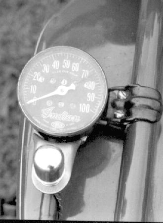 correct
mounting bracket, inner and outer drive cable, right angle drive unit,
pinion gear, road gear and maybe a light for good measure. Even if you
are lucky enough to find all the parts, what are the chances that you'll
get an accurate reading? I'd rather bet that Indian will rise again.
correct
mounting bracket, inner and outer drive cable, right angle drive unit,
pinion gear, road gear and maybe a light for good measure. Even if you
are lucky enough to find all the parts, what are the chances that you'll
get an accurate reading? I'd rather bet that Indian will rise again.
A 100 mph Corbin speedomter on an early Indian 4
The Corbin speedometer was manufactured
by the Corbin Screw Corporation, New Britain Connecticut, beginning around
1910. Corbin was the successor to the American Hardware Corporation, which
itself was founded about 1878. Most early Corbin speedometers were produced
under the Corbin-Brown name, but some may have been produced under the
Brown name alone.
The drive mechanism for motorcycle
speedometers was designed to be as accurate and trouble free as possible.
An external "road gear" clamped to the spokes drove a smaller gear attached
to a right angle gear unit. This equipment translates circular wheel motion
to the speedometer drive cable. Almost all speedometers of this period
were driven from the rear wheel. An exception appeared around 1915 when
Corbin developed a front wheel drive arrangement. This system was only
available for about five years, possibly due to problems with the drive
cable binding when the fork was turned sharply. From this point on, all
Corbin speedometers were driven from the rear wheel.
The speedometer heads themselves will
not be discussed in detail here. A thorough history of them could fill
an entire book, I'll leave this subject to someone more qualified than
myself. Our area of interest is the drive line components and how to make
them work together.
Assembling an accurate speedometer
is not a simple proposition, it requires a properly calibrated drive mechanism.
Many variables between the speedometer and the road must be taken into
consideration when setting up the drive line.
To determine the appropriate components
for your motorcycle, consult your motorcycle's parts book (if it was originally
equipped with a Corbin) or a Corbin handbook which lists your machine.
Corbin handbooks provide detailed information on the appropriate parts
for many motorcycles of the period. Armed with this information, you know
what is needed, right? Well..., there is one fly in the ointment. While
today's reproduction tires are of far better quality than originals, they
are not necessarily identical to what Corbin used in their original calculations.
Their circumference may be significantly different, creating a serious
impact on speedometer accuracy.
DRIVE LINE COMPONENTS
TIRE SIZE The circumference of the tire is what
you need to know here. Regardless of the tire's stated 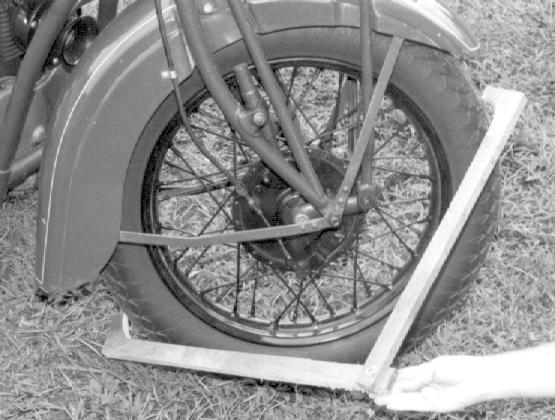 size,
measure to be sure. Tire wear and inflation also have a bearing on tire
circumference. Start by measuring the diameter from outside to outside
edge at the centerline of the tread. Use a large caliper to gauge the distance,
then measure the caliper. The largest caliper in my tool box only goes
to twenty inches. So I made a simple one from two pieces of 1x4 lumber.
Using this tool, I was able to measure within a 16th of an inch. A yardstick
can be used, but the chance of inducing error is increased because you
must still eyeball the yardstick to the centerline. The formula used to
determine circumference is:
size,
measure to be sure. Tire wear and inflation also have a bearing on tire
circumference. Start by measuring the diameter from outside to outside
edge at the centerline of the tread. Use a large caliper to gauge the distance,
then measure the caliper. The largest caliper in my tool box only goes
to twenty inches. So I made a simple one from two pieces of 1x4 lumber.
Using this tool, I was able to measure within a 16th of an inch. A yardstick
can be used, but the chance of inducing error is increased because you
must still eyeball the yardstick to the centerline. The formula used to
determine circumference is:
3.14 x Tire Diameter = Tire Circumference
Measuring tire circumference with home made calipers.
ROAD GEAR or REAR WHEEL SPROCKET Right angle drive
Corbin speedometers were driven by what Corbin termed a "road gear", clamped
to the spokes of the rear wheel. Road gear drive was later r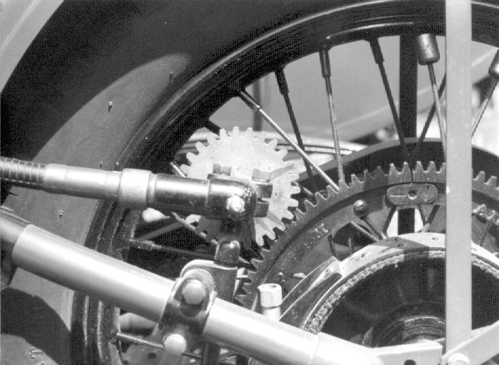 eplaced
by sprocket drive, which in turn was replaced by axle drive. Indian used
a road gear on the Chief through 1928 and the Scout through 1927. The Indian-Ace
and later Fours through 1930 were sprocket driven. Sport Scouts used sprocket
drive through 1939. Harley-Davidson used road gears through 1929, then
changed to sprocket drive for two years.
eplaced
by sprocket drive, which in turn was replaced by axle drive. Indian used
a road gear on the Chief through 1928 and the Scout through 1927. The Indian-Ace
and later Fours through 1930 were sprocket driven. Sport Scouts used sprocket
drive through 1939. Harley-Davidson used road gears through 1929, then
changed to sprocket drive for two years.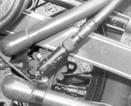 Harley, with only two exceptions, used right angle drive units until 1932
on their big twins. The exceptions were 45s and singles which used them
through 1933. Excelsior and Henderson used road gears until the end of
production in 1931. Road gears were available in a wide variety of sizes
from 64 to 110 teeth.
Harley, with only two exceptions, used right angle drive units until 1932
on their big twins. The exceptions were 45s and singles which used them
through 1933. Excelsior and Henderson used road gears until the end of
production in 1931. Road gears were available in a wide variety of sizes
from 64 to 110 teeth.
On the left is a road gear driven drive unit, on the right a sprocket driven unit
PINION GEAR This is the small fiber gear on the right angle drive unit driven by either the road gear or the sprocket. There are two styles of pinion gears; small teeth for use with a road gear and large round teeth for use with a rear wheel sprocket. The change to rear sprocket drive simplified the installation procedure and eliminated the road gear, but it also brought with it an unforeseen problem - vibration. Harley and Indian eventually provided soft rubber gears in lieu of fiber ones in an effort to reduce this problem.
RIGHT ANGLE DRIVE UNIT
This unit transmits gear rotation 90 degrees to the speedometer
drive cable. One must be careful with right angle drive units as they came
in at least three different ratios. The road gear equipped models were 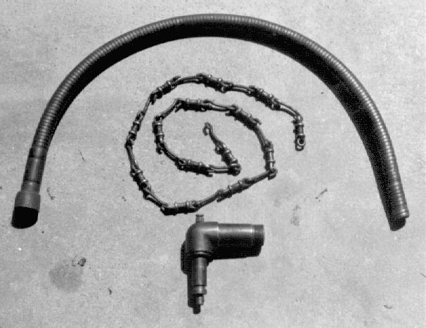 probably
all 1:1 ratio. On sprocket driven models it was impractical to change the
sprocket to get the desired ratio, so the drive units were made in different
ratios such as 14:15, 1:1 and 15:14. To determine what you have simply
rotate the fiber gear 15 times and watch the output spline. If it rotates
exactly 15 times as well, it's a 1:1, if it only rotates 14 times, it's
a 15:14, if it rotates approximately 16 times, it's a 14:15. Early (teens)
drive units had an internal clutch that allowed the drive line to be disengaged
for maintenance. Alemite grease fittings were added sometime after 1920,
appearing in at least 2 different locations.
probably
all 1:1 ratio. On sprocket driven models it was impractical to change the
sprocket to get the desired ratio, so the drive units were made in different
ratios such as 14:15, 1:1 and 15:14. To determine what you have simply
rotate the fiber gear 15 times and watch the output spline. If it rotates
exactly 15 times as well, it's a 1:1, if it only rotates 14 times, it's
a 15:14, if it rotates approximately 16 times, it's a 14:15. Early (teens)
drive units had an internal clutch that allowed the drive line to be disengaged
for maintenance. Alemite grease fittings were added sometime after 1920,
appearing in at least 2 different locations.
A right angle drive gear, dumb-bell link chain and
outer case
SPEEDOMETER CABLE Corbin used two types of drive cables. Most commonly available was the 5/8" OD cable. This used a unique inner cable made of "Dumb-bell links", actually more like a chain than a cable. Corbin was quite proud of this design because of its smooth operation and resistance to kinking. The other cable had a 1/2" OD and used the more common wire wound inner cable. The 1/2" cable may have been available on special order through the 1930s.
SPEEDOMETER HEAD This is the speedometer itself.
Corbin made quite a variety of these over the years. Variations include,
but are not limited to 30, 60, 80, 100, 110 and 130 mph, 100, 130, 160
kph, luminous dial (beginning about 1920), maximum speed hand, tripmeter
and others. It is beyond the scope of this article to discuss specific
motorcycle applications. Generally speaking, speedo heads that have nickel
plated bodies are from the teens, 60-100 mph and 100-130 kph dials were
available in the mid 20s, 110 mph and 150 kph came into use in the mid
1930s. Internal lighting generally became available about 1934, but was
available on special order beginning in the late 20s. The important thing
we need to know in order to get an accurate speedometer reading is the
required number of input revolutions per mile of travel. Most likely, all
Corbin speedometers used a standard input 2,560 revolutions per mile.
DETERMINING DRIVE RATIOS
Let's walk through an example of how to determine the gearing necessary for an accurate speedometer. I'll use my 1930 Indian Four. This machine already has a complete and operating speedometer, but it's not reading accurately (sound familiar?). I want to determine what size fiber pinion gear is necessary to make it read accurately. The known quantities are: Tires are 4.00 - 18 Coker drop center diamond tread; 36 tooth rear sprocket; 1:1 ratio right angle drive unit; and a 2,560 revolutions per mile speedometer head.
1. Inflated to 35 psi, the tires have a diameter of 26.0" measured with my home made calipers. Now take this measurement and calculate the circumference.
26" (diameter) x 3.14 = 81.64" Circumference
The circumference of the Coker 4.00 - 18" tire inflated to 35 psi is 81.64 "
2. Convert the circumference from inches to feet.
81.64" / 12” = 6.803'
3. Now determine the tire revolutions per mile (TRPM):
5280'(one mile) / 6.803' = 776.128 TRPM
4. Now comes the tricky part, determining apparent TRPM. Apparent TRPM is the output from the right angle drive unit. Use the appropriate formula for your drive unit ratio.
A. 1:1 ratio drive unit: This is what my Indian Four has and it's the easy one. Apparent TRPM is the same as TRPM from step 3 (776.128).
B. 14:15 ratio drive unit: Take the tire revolutions per mile from step 3 (776.128) and multiply it by 1.071. The result is the apparent TRPM.
776.12 x 1.071 = 831.233 (APPARENT TRPM)
C. 15:14 ratio drive unit: Take the TRPM from step 3 (776.128) and multiply it by .933. The result is the apparent TRPM.
776.128 x .933 = 724.127 (APPARENT TRPM)
5. If you made it this far, don't quit now, you're in the home stretch. Determine the ratio between APPARENT TRPM from step 4. A, B or C and the revolutions required at the speedometer head using the following formula:
2560 / APPARENT TRPM = RATIO
A. 1:1 ratio drive unit: 2,560 / 776.128 = 3.298
B. 14:15 ratio drive unit: 2,560 / 831.233 = 3.079
C. 15:14 ratio drive unit: 2,560 / 724.127 = 3.535
4. Lastly, determine the fiber pinion gear size. Divide the number of teeth on the sprocket or road gear by the ratio determined in step 5.A, B or C. The 1:1 drive unit of my Indian is:
36 / 3.298 = 10.91 (fiber pinion gear size).
Since gears are made in whole number sizes, round 10.91 up to 11. An 11 tooth fiber pinion gear will provide the most accurate speedometer reading.
If by now you haven't exhausted your
calculator's batteries, you've done well. While this may seem complicated,
it really is quite simple. Just take your time and make sure your calculations
are correct. You'll be rewarded with an accurate speedometer that will
provide many miles of service. Good Luck!
Many thanks to Doc Schuster for assistance with this article.
APPENDIX
Early Corbin speedometer and driveline resources
1. Dr. Fred J. Schuster
24183 Nichols Rd.
Monroe, OR. 97456
Right angle drive units, brackets and
cables
2. Mr. George Breitung
4955 Vesper Dr.
Everett, WA. 98203
Fiber pinion gears
3. Mr. Woody Carson
760 East Dale Dr.
Ft. Collins, CO 80524
Speedometer head mounting brackets
4. Mr. Peter R. Heintz
775 Walnut Bend Rd.
Cordova, TN 38018
Speedometer head service
Return to Splitdorf Generator & Magneto main page