This article was originally
published in the Spring 1997 issue of
The Antique Motorcycle
The official publication of the
Antique
Motorcycle Club of America
The Splitdorf Generator -
Identification, Care and Feeding
Photos by Kim Koronas
The Splitdorf generator has
long been a source of mystery, frustration and darkness to those who ride
and restore motorcycles of the early days. Splitdorfs were standard equipment
on such notable steeds as Ace, Indian, Cleveland, Excelsior, Henderson,
Reading-Standard and Militor. Today they are rarely found complete and
undamaged, much less in operating condition.
WANTED: Splitdorf generator for 1926 Indian Scout....
How many times have you seen an ad
like this? When an ad like this appears, I often wonder if the author knows
which splitdorf generator he needs. Splitdorf manufactured many different
motorcycle generators over the years. With a little research, identifying
the correct one for your machine should not be too hard. Locating one might
be a different matter. Patience, perseverance and good old fashion luck
must be a constant companion throughout your search.
If the original Splitdorf is still
on your machine, consider yourself fortunate. Many continue to give long
and admirable service, but others perished of natural causes such as worn
brushes, armature insulation breakdown or a badly worn commutator. Others
may have died by more violent means such as a shorted electrical system,
collision, or moisture intrusion and years of corrosion. As a result, a
variety of generators may have perched on your motorcycle over the years.
The first thing to do is determine which model is correct for your machine.
Begin with your parts book, service manual and sales brochure. Close up
period photos are very helpful as well. If your machine was originally
equipped with a Splitdorf generator, a Splitdorf manual was probably included
with the motorcycle as well.
IDENTIFICATION
A Splitdorf is a Splitdorf, right?....
Well, not exactly. The Splitdorf Electrical Co. of Newark, New Jersey manufactured
at least 12 different motorcycle generators from 1918 to 1931. There are
at least 4 basic types; the DU-1, DU-3, DU-5 and DU-7. Not including the
early Splitdorf Mag-Dynamo unit introduced about 1915. This combination
magneto and generator unit put out a maximum of 3 amps at 7.5 volts at
1400 engine RPM. All Splitdorf generators can be identified by the model
number stamped on the cutout cover. But be careful, covers were easily
lost and often replaced with whatever was available. For example, it is
not uncommon to see a DU-1 with a DU-5 cover. DU-7 covers can be used on
previous models but, because their commutator heads are about 1/16" larger
in diameter where the cover slips over, they will fit loosely. They also
have a different retaining screw pattern, consequently only one screw will
find a hole. Rotation on all models is determined looking at the pulley
or drive end and is indicated by an arrow stamped into the drive end of
the main body or in the case of the DU-1, on the drive head. However, more
than a few have had their rotation reversed over the years. To determine
rotation, look at the third (adjustable) brush under the cover. If it's
a clockwise (CW) rotation the adjustable brush will be closer to the top,
positive brush (near the terminal post). If it's a counter-clockwise (CCW)
rotation the third brush will be closer to the bottom (negative) brush.
Some generator bodies were evidently
tin plated to ensure good electrical contact with the mounting bracket.
This is rarely seen on surviving generators due to deterioration. However,
it is visible in period photos and Splitdorf literature. Upon disassembly
and careful inspection of many generators, I have found traces of this
plating inside the bodies as well as on the outside, under the original
paint. The outside of the body was painted black, approximately 1.2" from
the commutator end and .50" from the drive end, leaving a tin plated stripe
where the mounting clamp attaches. The exposed plating apparently deteriorated
faster than the painted area. After disassembly and a thorough cleaning
it is sometimes possible to see where the original stripe was by the increased
amount of pitting. The factory was apparently not too concerned with the
exact dimensions of the stripe, as I’ve seen some dimensional variation
between generators. The cutout cover and drive head were also painted black.
MODELS
The following is compiled from Splitdorf brochures,
various motorcycle parts, service and sales literature, as well as hands
on examination of many generators. While not necessarily all inclusive,
it represents the most commonly used models of the period:
DU-1 The DU-1 appeared about 1918 as a successor to the troublesome Splitdorf Mag-Dyno unit. It’s a 2 pole, shunt wound, current regulated design and was made in left and right hand rotation. It was rated at a maximum 4 1/4 amps at 7.5 volts at 1800 rpm. Unlike later models, it used the same size bearing at each end. Armatures were unique for each rotation. Rotation is indicated by an arrow stamped into the drive head behind the pulley. Externally the DU-1 looks very similar to the DU-5. The drive head is retained by two studs with nuts that pass through the body to the cast iron commutator head. The drive end bearing oiler is located on the outside of the body, at the drive end. Because of this vulnerable location, oilers are often missing today. The drive shaft has an OD of .375" and is made for a straight hole pulley. DU-3, DU-5 and DU-7 drive shafts have a .512" OD and use a pulley with a 12 degree tapered hole. The DU-1 used a mechanical cutout (discussed later). Variants include:
DU-1 CW rotation (Henderson, others)
DU-1 CCW rotation (Indian Powerplus/Scout, others)
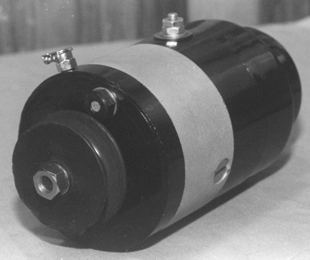 A
DU-1 restored by the author. Note the bakelite pulley and oiler mounted
on the outside of the body.
DU-3 This is a rare model that appeared around 1921. It used a complicated electrical cutout assembly completely unlike the electrical cutout used on later models. The drive end oiler was moved to a more protected location on the drive head. It looks almost identical to the DU-5 with the notable exception of the cutout cover. The DU-3 cover is straight sided, that is there is no stepped bulge as with all other models. This unusually large cover was necessary to house the electrical cutout. If the original Splitdorf bulletin is to be believed, the DU-3 would regulate output to 6 1/2 volts and 3 1/2 amps at 6000 rpm! This is more than 3 times the rpm of the DU-1 and more than twice that of the DU-5. Whether this is a misprint or the generator was intended for very high speed work I do not know. But I wouldn’t want that little dynamo spinning at 6000 rpm between my legs!
DU-5 The DU-5 appeared around 1922 (author's note: recently uncovered documentation tells me that the DU-5 actually became available in late 1920) and was made more robust and with larger bearings and drive shaft than the DU-1. Maximum charging rate is 3-3/4 to 4-1/4 amps, 7.5 volts at 1800-2500 generator rpm. It was designed to operate with a 6 volt, 15 amp battery. Armatures were identical for both rotations, except for the DU-5H which used a longer drive shaft. Some armatures are marked with the month and year of manufacture, e.g. "2-27". DU-5s were used throughout most of the 1920s and seem to be the most common model encountered today. All DU-1s and many DU-5s used the same mechanical cutout. Around 1925 Splitdorf developed the "A-10 Electrical Cutout" as a replacement for the mechanical one. A DU-1 or DU-5 can be quickly distinguished from the DU-7 by the relatively smaller size of the bulge of the cutout cover. Diameter of this bulge is about 2-1/2". DU-5 variants include:
DU-5 CW rotation (Excelsior, Henderson Deluxe,
Ace, Indian Ace)
DU-5 CCW rotation (Indian Scout/Prince, early
Henderson KJ)
DU-5E CCW rotation (Excelsior)
DU-5H CW rotation (Indian Chief)
DU-5C CW rotation (Cleveland)
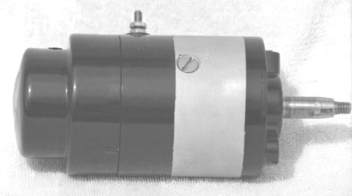
DU-7 The DU-7 was developed in late 1927 and appeared in early 1928. It was a significant improvement over the DU-5 for several reasons. The cast iron commutator head of the previous models was prone to breakage under rough service. Consequently, an aluminum head was developed which was lighter and more durable. With the end cover removed this assembly is easily identified. A 3 amp fuse was incorporated into the field coil circuit to protect the coils from excessive current. Maximum output was increased to 5 1/2 amps at 3500 rpm. A larger, improved electrical cutout was developed to handle the higher current. The cutout cover bulge was correspondingly enlarged to 2-15/16". DU-7 variants include:
DU-7 CCW rotation (Indian 101 Scout, Prince,
Henderson KJ, KL)
DU-7 CW rotation (Indian Ace/401/402)
DU-7 CW rotation (Cleveland)
DU-7H CW rotation (Indian Chief)
Other models may exist, either as prototypes or for limited application. An example of this is a DU-2, which may have been used for a period on early Ace motorcycles. The Ace literature I’ve reviewed only mentions “splitdorf generator”, but not a specific model. A noted Ace collector tells me he has seen a DU-2 among parts obtained from a former Ace dealer. It makes sense that models would be numbered consecutively. But up to the present time I have not seen any other models or a reference to one in any Splitdorf literature.
CUTOUTS
The cutout is a device used to prevent
the battery from discharging back through the generator when the armature
is not rotating fast enough to produce sufficient current. The two general
types of cutouts used on Splitdorf generators are mechanical and electrical.
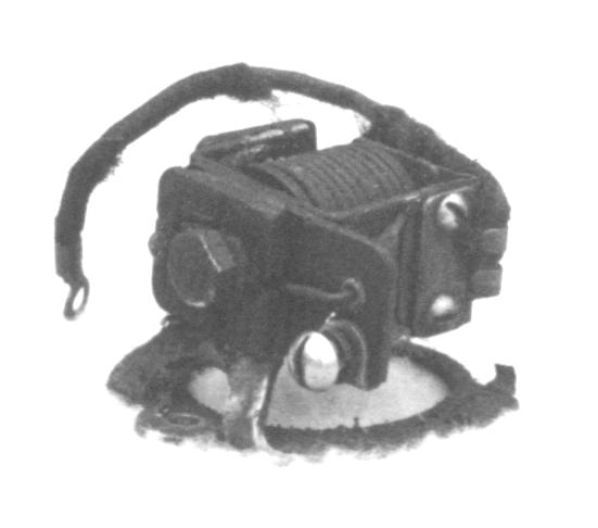
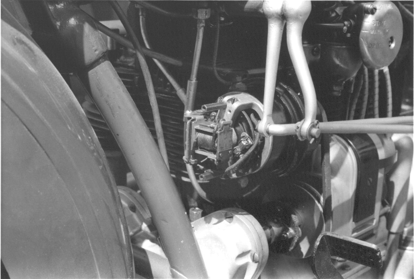
Mechanical Cutout The DU-1s and early DU-5s use a mechanical cutout (sometimes called a centrifugal cutout) mounted on the commutator head and attached to the end of the armature shaft. A small, spring loaded doughnut shaped piece is attached to the armature shaft. With the engine off or at idle, this doughnut is tilted by spring pressure. When armature speed increases, centrifugal force causes the doughnut to flatten out perpendicular to the shaft. This in turn causes the points to close, allowing current to flow from the generator to the electrical system. When speed drops, spring pressure overcomes centrifugal force and the doughnut tilts back, causing the points to open. This was a sound design, but two potential problem areas exist. First; As a mechanical device, the cutout is subject to wear. It must be properly adjusted with a point gap of .015" to .020", and lubricated routinely, but sparingly. Second; output current has no effect on cutout operation. If the generator fails electrically, the points will still close when armature speed increases. If this happens, the battery will rapidly discharge through the generator to ground, possibly causing damage.
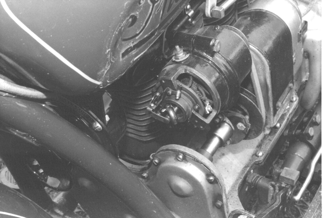
Electrical Cutout Late model DU-5s and all DU-7s used electrical cutouts which eliminated the problems encountered with the mechanical one. Splitdorf developed the "A-10 electrical cutout" around 1925 for the DU-5. The A-10 could be back-fitted to any Splitdorf model prior to the DU-7 except the DU-3. Installation simply required the extended armature shaft previously used to drive the mechanical cutout to be cut off, the new cutout attached and wired. The A-10 cutout is not the same as the DU-7's cutout. The latter used a larger, more robust model designed to handle the additional current output of the DU-7. Contact points on either one should be set at .015 - 020". Indian service shot #35, dated November 5th, 1929 provides detailed adjustment procedures for the DU-7 cutout and is an excellent reference. Early DU-7 electrical cutouts were prone to vibration damage. In late 1929 or early 1930 Splitdorf offered free replacement of the defective cutouts with a more rugged unit. The replacement units were all stamped on the bottom with a date, defective units were not dated.
MAINTENANCE
The Splitdorf generator gave good
reliable service under normal use. But under arduous conditions several
weak points emerged which have contributed to a bad reputation. Under the
conditions we ride our machines today, a properly restored splitdorf generator
can provide years of reliable service.
The lack of a fuse on models prior
to the DU-7 may have contributed to the demise of more generators than
any other cause. By design, the Splitdorf is a shunt wound, current regulated
generator. Normally a small portion of the generated current passes through
the field coils. An open circuit from a broken generator lead or disconnected
battery will cause all generated current to flow through the field coils.
If this occurs, damage to the field coils and armature may result. The
DU-7 finally overcame this problem by incorporating a 3 amp fuse into the
field circuit. It's always a good idea to look at your ammeter after shutting
down the engine and turning off all lights. The ammeter should read zero.
If the points stick closed (which can happen, I know!), a high amperage
discharge will be seen. If it becomes necessary to operate an unprotected
generator without a battery in the circuit, ground the output from the
generator. To do this, remove the wire from the generator terminal post
and replace it with a ground wire attached to the frame. This will allow
current to flow out of the generator directly to ground, not through the
field coils. On a DU-7, the fuse can be removed to provide similar protection.
The armature runs on thrust type ball
bearings. As per the Splitdorf manual, they require 4-5 drops of light
oil every 400 miles. But go easy with the lube, add too much and you'll
end up with a soggy, shorted generator. Actually, bearings that have been
packed with modern grease can probably go years with no further lubrication.
Fortunately, new bearings are still available for the DU-5 and DU-7, although
somewhat costly and difficult to obtain due to their limited application.
I have been unable to locate a source for the original DU-1 bearings, but
I’ve have had good service using a modern sealed radial bearing as an alternative.
If it is necessary to replace the bearings, be very careful when removing
the races. This is especially true for the DU-7 commutator end outer race.
Located in the aluminum commutator head, it can be difficult to extract
without damaging the aluminum. Careful application of heat can help here.
The DU-1 and DU-5 were primarily designed
to keep the battery charged or power the lights, not necessarily both.
Depending on the current draw (i.e. number of lights turned on), generator
output may or may not be able to keep up with demand. As electric lighting
became more popular, greater demands were made on the electrical system.
The DU-7, with it's 5-1/2 amp maximum output was designed to meet these
demands. However, operating the generator at maximum output for an extended
period creates considerable heat which may lead to reduced generator life.
Although Splitdorf touted their generator’s maximum output, they also advised
against running continuously at maximum output.
The key to a healthy electrical system
is proper matching of the generator output to electrical demand. The is
an easy adjustment, however the actual output will be unique to each generator.
Output is increased by moving the third brush in the direction of armature
rotation. If available, use a high quality ammeter when adjusting output
current. While adequate for daily use, the original equipment ammeter is
probably not accurate enough for precision adjustments. Ideally, the generator
should provide a charge of 1 to 1 1/2 amps to keep the battery charged.
If most of your riding is during daylight hours, you'll probably want to
adjust your generator output with all lights off. However, if you do a
lot of night riding, adjusting the output with the lights on, and riding
with them on day and night may be preferable. If the generator does not
provide sufficient current to meet demand, additional current will be drawn
from the battery. This is OK for short periods, but will soon suck the
life out of your battery if operated for an extended period.
A few do’s and don’ts to keep you Splitdorf alive and well:
Do:
1. Keep generator output current as low as possible
to meet your motorcycle’s needs.
2. Keep the cutout properly adjusted and lubricated
(mechanical only).
3. Adjust the drive belt for a taught but not tight
fit. A loose belt will cause the generator to appear not to charge.
4. Ensure generator is properly grounded.
5. Check your ammeter for a zero reading after
shutting off the machine.
Don’t:
1. Operate the generator at maximum output or above
5 amps for an extended time.
2. Operate the generator without a battery in the
circuit or a ground wire attached.
3. Run the belt too tight. Remember the bearings
supporting the armature are pretty small and in the case of the DU-1 a
small diameter drive shaft which can be easily bent.
4. Over oil the bearings. A little goes a long
way. Excessive oiling can ruin a generator.
5. Run the generator in the opposite direction.
Verify the generator’s designed rotation before operating.
6. Allow excessive end play to develop in the bearings.
Excessive end play also means excessive side play of the armature. Clearance
between the armature and the pole shoes is only about .012” - .015”. Too
much side play and the armature may strike the pole shoes.
NOTES ON INDIAN APPLICATIONS
Indian began using the DU-1 on the
electrically equipped 1918 Powerplus, followed by the Scout in 1920. The
DU-5 became available in the early 1920s on all models. Indian announced
the DU-7 on March 5, 1928 in Service Shot #15. The 101 Scout was released
in February of 1928, only weeks after the DU-7 was announced. Service shot
#41, dated January 26th, 1930 discusses the Auto-lite generator used on
"various models of Indian motocycles". IMPORTANT NOTE; This service shot
is apparently dated wrong. It should probably be dated January 26, 1931
(one year later!). After a lengthy discussion with George Yarocki and in
light of the sequential numbering and dates of Service Shots before and
after this one, it looks as though the original Indian typist slipped by
one (very important) digit. This "various models of Indian motocycles"
probably refers to the Scout and Four. The Chief's generator was mounted
in front of the engine, driven by the timing gears. Because the Auto-lite
was larger in diameter than the Splitdorf, it could not be fitted without
significant modification to the engine cases. The Chief's generator, DU-5H
or DU-7H is easily recognized by its longer armature drive shaft, approximately
1.5" vice 1.0” on other models. As a result, the chief continued to use
the DU-7H through the 1931 model year, after which the mounting was moved
behind the engine and the Auto-lite was adopted..
1931 models began production in March or April
of 1931. Considering Indian's policy of "No yearly models, but constant
improvements", and service shot #41, the last month or two of 1930 Scout
and Four production probably used the Auto-lite generator. Let me caveat
this with Indian's well known practice of using up parts on hand. Indian
was not about to waste anything. As such, it is possible that DU-5s and
DU-7s were still used after the dates indicated.
NOTES ON HENDERSON APPLICATIONS
The DU-1 was used beginning in 1920
with the model K. The DU-5 superseded it in the early 1920s. These were
both clockwise rotation. The design of the new KJ model in 1929 required
a change in generator rotation to counter-clockwise. The KJ initially used
the DU-5, then the DU-7 when it became available. The DU-7 probably first
appeared on the high performance KL in May of 1930. In 1931 the Auto-lite
generator replaced the Splitdorf until the end of Henderson production.
CONCLUSION
The Splitdorf generator has been obsolete
for well over 60 years. As a staple of the American motorcycle industry
in the years between the First World War and the Depression, it provided
safe and efficient lighting to thousands of motorcyclists. It’s dependability
no doubt contributed to the demise of unreliable and potentially dangerous
acetylene lighting. By necessity they were small and less robust than their
brethren automobile generators. As a result of this and increased exposure
to the elements, they are rarely found in operating condition today. More
than a few disparaging remarks have been uttered, perhaps unfairly about
the Splitdorf generator over the years. When properly maintained, they
were probably no less reliable than automobile generators of the period.
Although some shortcomings have come to light over the years, the basic
design of the Splitdorf generator has proven to be sound and reliable.
Unless physically damaged, they can usually be restored to provide many
more years of reliable service.
