![]()
![]()
![]()
![]()
![]()
![]()
![]()
![]()
![]()
![]()
![]()

Solid State Voltage Regulator
for
DU Series Splitdorf Generators
Now you can turn on your lights any time!
Gene Harper 9350 W. Grandview Ave. Arvada, Colorado 80002 www.splitdorfreg.com
Installation and Operating Instructions
DU Series Splitdorf
Generator
Solid State Voltage Regulator
APPLICATION
This solid state voltage regulator is specifically designed to fit Splitdorf DU model generators, including DU-1, DU-5 and DU-7, both clockwise and counterclockwise rotation. These generators were commonly used on Indian, Henderson, Excelsior and other motorcycles (except Harley Davidson) from 1918-1931. Do not attempt to adapt this regulator to other applications, as it may not perform correctly and may very well damage or destroy the generator, or regulator. See our web site for other regulator applications.
PREPARING FOR INSTALLATION
Before proceeding with installation, insure that the generator is functioning properly. Visit our website: www.splitdorfreg.com and click on the link directing you to “Steve Blancards original website” for more information on rebuilding and maintaining your Splitdorf generator. Next, determine the maximum potential output of the generator. This test can be performed with the generator on or off of the motorcycle, with or without the original cutout assembly in place.
1. Determine the direction of generator rotation for your particular application, either clockwise or counterclockwise. Generator rotation is ALWAYS referenced when looking at the drive end of the generator.
2. See the wiring diagrams in Figure 1 on the next page. Note that these diagrams are looking at the commutator or brush end of the generator. Locate the two diagrams appropriate for your application, either clockwise, or counterclockwise rotation. Mark these diagrams and study them carefully; you will refer to them later in the installation process. Disregard the diagrams that do not apply to your application.
3. Remove the end cover from the generator. Locate the third or adjustable brush and remove the wire attached to it. Temporarily label this wire with#3 for now (third brush). This should be one of the two leads which attach to the field windings.
3.1. For Clockwise Rotating Generators Only: Using a suitable jumper wire, temporarily connect this wire to the positive brush terminal.
3.2. For Counterclockwise Rotating Generators Only: Attach this wire to the generator chassis, thereby grounding it.
4. Connect a fully charged 6 volt battery and a suitable ammeter to the generator. If the generator is installed on the motorcycle, use the existing wiring and ammeter for this test.
4.1. Connect the positive brush terminal to the negative ammeter terminal, and then connect the positive ammeter terminal to the positive battery terminal.
4.2. Connect the negative battery terminal to the generator chassis, or ground.
4.3. The generator should attempt to spin at this time, much like an electric motor. If so, disconnect the ground wire from the battery and proceed to the next step. If not, double check your connections and polarity or repair the generator.
5. Spin the generator at approximately 3500 RPM. This can be easily accomplished if the generator is still mounted on the motorcycle. An alternative method is to spin the generator shaft in a lathe or drill press, noting the correct direction of rotation. Be sure to hold the generator body securely when performing this test as it could potentially spin loose and cause damage or injury.
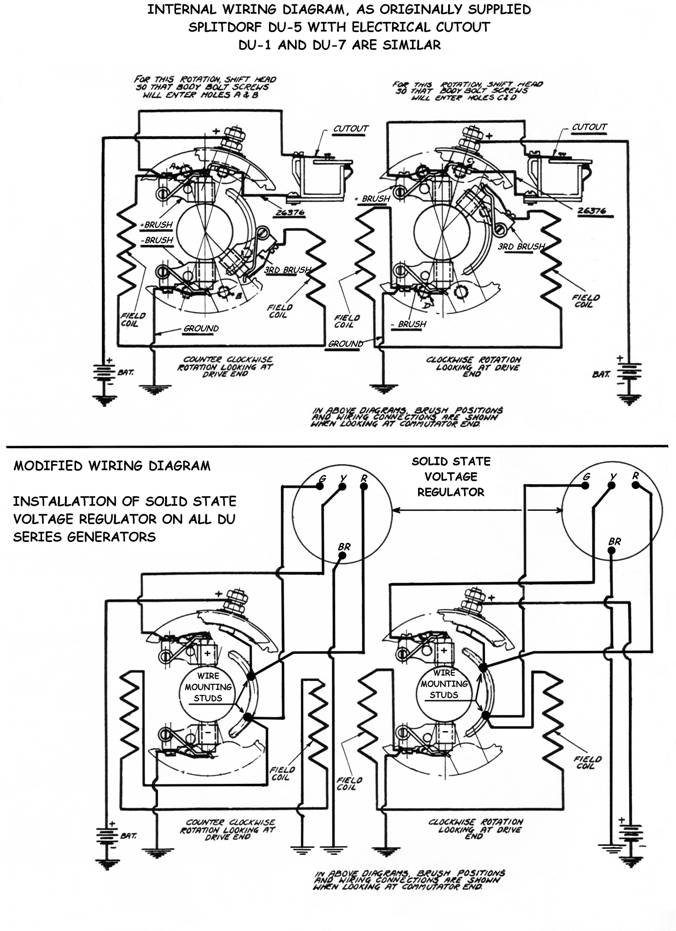
Figure 1: Wiring Diagrams for All Models
PREPARING FOR INSTALLATION, CONTINUED
6.
Once spinning, reconnect the wire which was disconnected in Step 4.3 to
the negative battery terminal. The ammeter should now register a charge rate
of at least 4.5 amps. Some generators may produce as much as 10 amps. Record this number, as it the
absolute maximum amount of power the generator is capable of producing.
generators may produce as much as 10 amps. Record this number, as it the
absolute maximum amount of power the generator is capable of producing.
7. If the generator registers a low current output or no current output at all, double check all connections and re-polarize the fields, as in step # 6 above. If the output is still below 4.5 amps, the generator is in need of repair.
8. Refer to Steve Blancards web pages to assist you in the repair or overhaul of the generator. Go to: ..\Blancard\Blanchard.htm/Blancard.htm for more information.
9. Locate and correct any problems before proceeding. Remember, the Splitdorf Solid State Voltage Regulator cannot fix a broken generator, but can make a good generator work much better!
DO NOT PROCEED WITH THE INSTALLATION OF THE SOLID STATE VOLTAGE REGULATOR UNLESS THE GENERATOR IS IN GOOD WORKING CONDITION AND CAN SUPPLY AT LEAST 4.5 AMPS OF CONTINUOUS OUTPUT!
INSTALLATION OF THE SPLITDORF SOLID STATE VOLTAGE REGULATOR
For All Models:
1. Remove the generator from the motorcycle.
2. Remove the entire cutout assembly. Note: If the cutout was previously replaced with a diode, remove the diode. If equipped with the older style centrifugal cutout, the armature shaft will need to be cut off flush with the commutator bearing housing in order to allow room for the new regulator assembly. Be careful to keep all metal shavings from the cutting operation from falling into the generator, especially the bearings! Set the pieces aside as they will no longer be needed.
3. Remove the two screws attaching the third brush holder assembly to the insulator plate. Remove the third brush assembly. If you have a DU-7 Model, remove the fuse holder as well. Set these pieces aside as they will no longer be needed.
4. Refer once again to the appropriate wiring diagram in Figure 1 for your application. Note that the wiring diagrams refer to the commutator end of the generator.
5. For Counterclockwise Rotating Generators Only: It will be necessary to reverse the connections of both field winding wires. See Figure 1, left side of diagram. Proceed as follows:
5.1. Locate the field wire that was previously attached to the third brush holder, now labeled #3. This wire must now be grounded, either to the negative brush terminal or to the chassis of the generator.
5.2. Next locate the field wire which is attached to the positive brush holder (the positive brush is the one closest to the generator output stud on the top of the case)
5.3. Remove the field wire from the positive brush holder. Label this wire “Field.” This field wire will be attached to the regulator later. It may be necessary to extend the field wire to allow it to reach the mounting stud (described in Step 7 below). If necessary, solder a lead onto the field winding wire and insulate with shrink tubing. Be sure to route this wire in such a way that it will not be damaged by the rotating armature or pinched.
For All Models:
6. Polarize the field windings using a fully charged 6-volt battery. Using jumper wires connect the negative battery terminal to the generator chassis. Momentarily connect the positive battery terminal to the remaining field wire which should not be connected to anything else at this time. You should notice a small spark when disconnecting the positive wire. Remove the grounding wire. If it becomes necessary to re-polarize the fields after installation of the regulator: with the battery connected to the generator, momentarily connect the red “BATTERY” wire to the green “FIELD” wire using a suitable jumper.
7. Use the now empty slot in the insulator plate (the one that used to house the adjustable third brush) to install two mounting studs for new wire connections (see Figure 2). Space these far enough apart so that none of the wire connections can contact the chassis, or each other. These two studs will be used to attach two of the regulator wires to the field and battery stud output wires. For each stud, use one #6-32 x ¾” bolt, two flat washers, one lock washer and two nuts (included with regulator). Install the bolt, flat washers and one nut on the insulator plate and tighten them securely to locate them. The remaining nut and lock washer will be used to secure the wires onto the stud. Using an ohmmeter, test both studs to be sure they are insulated from the generator chassis. This is critical on DU-7 models which have a steel plate in between the two fiber insulator plates.
8. Mounting the regulator in the generator cover must be done properly in order to insure adequate cooling and operation of the regulator. This will require a heat conducting paste (included) and a high temperature automotive RTV silicone sealant, such as Permatex Red RTV gasket sealer. Warm the package of thermal paste by placing it in your pocket or a container of hot water while performing the following steps.
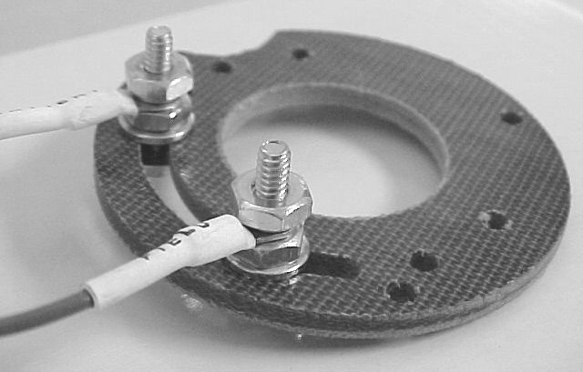
Figure 2: Mounting Studs Installed on Insulator Plate (DU-1 and 5 style)
8.1. Thoroughly clean the inside of the cover assembly to remove all traces of grease and rust. Bead blasting is preferred. Clean the exterior of the regulator to remove any grease or severe oxidation if necessary.
8.2. Carefully tap out any dents in the rounded end of the cover to allow the regulator to sit evenly in the cover.
8.3. For DU-7 Models Only:
8.3.1. Remove the two cover mounting studs from the generator end plate. If the studs are difficult to remove, the generator must be disassembled because the studs were originally staked in place from the bottom. Carefully grind the stake marks off and remove the studs.
8.3.2. Install the studs into the cover using the cover mounting screws. Be sure these studs are lined up straight on the cover.
8.3.3. Cut two pieces of a large diameter drinking straw (or other suitable tubing) to the length of the stud and slip one onto each stud (see Figure 3). This tubing should fit loosely and cover the mounting stud but leave the threaded portion uncovered. The sleeves will act as a guide and allow the cap and regulator assembly to slip over the mounting studs when installed on the generator.
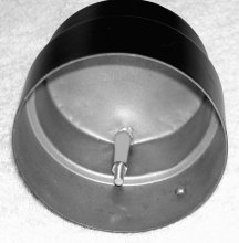
Figure 3: Cover With Tubing Assembly Installed on Mounting Studs
For All Models:
8.4. Cut off one corner of the plastic bag containing the heat conductive paste. Apply all of the paste to the center area of the brass regulator body. Next apply a bead of the RTV silicone to the outside diameter of the bottom of the brass regulator body.
8.5. Carefully lower the regulator assembly into the cap and center it by GENTLY holding the wires. Locate the three wires near what will be the top of the cap and the brown wire near the bottom. Exact placement of these wires is not critical; however, do not obstruct the oil hole in the cap of the DU-1 or -5 models. Press firmly on the black epoxy portion of the regulator to seat it evenly into the center of the cap, squeezing any excess RTV up and out the sides. Fill any voids between the sides of the brass regulator case and the cover with additional RTV. DU-7 models will require quite a bit more RTV to fill all of the void space between the regulator and cover, as well as around the straw sleeves covering the mounting studs.
8.6. Wipe off any excess RTV, leaving only a small bead on the top edge of the brass regulator body, enough to keep the regulator from coming out once it dries.
8.7. If the previous step was done properly, there should be a solid mass of heat conducting compound between the flat end of the brass regulator body and the rounded end of the cap. There should also be a solid bead of RTV holding the regulator in place on the sides. Once the regulator is “glued in,” let it sit overnight to cure before making the wire connections. Application of gentle heat will speed the curing process; however, excess heat may destroy the regulator. If you choose to apply heat, set the unit near a heater vent or use a blow dryer on the warm setting only, not hot.
9. Make the following wire connections from the solid state voltage regulator to the generator while supporting the regulator and cap assembly:
9.1. Yellow (+ brush): connects to the positive brush terminal, located closest to the output stud on the top of the generator.
9.2. Red (battery): connects to one of the newly installed stud terminals on the insulator plate. Also attach the wire from the generator output stud to this terminal.
9.3. Green (field): connects to the second new stud terminal along with the remaining field wire which is not grounded.
9.4. Brown (ground or chassis): connects to the generator chassis.
DO NOT LET THE CAP ASSEMBLY HANG BY THE REGULATOR WIRES ! DAMAGE TO THE REGULATOR MAY OCCUR
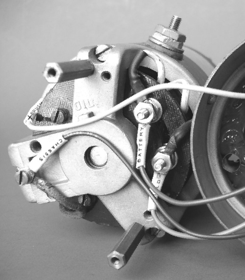
Figure 4: DU-7 Showing Wiring Connections
10. Remove the mounting studs from the cap assembly and reinstall them on the generator end plate (DU-7 models only). Install the cover using the original mounting screws. Be sure that all wire connections are tight, clean and well protected from shorting to ground or other wire connections. Also be very careful to route all wires in such a way as to avoid any damage from pinching under the cap or rubbing on the armature which could cause a failure of the regulator or generator.
11. Install the generator on the motorcycle and reconnect the generator output wire to the stud on top of the generator. Insure that the battery and all connections are in good condition and the battery is fully charged before proceeding.
OPERATION:
Based on the battery voltage, the generator can now charge only as much as needed. When the lights go on, generator output increases in an effort to maintain the desired battery voltage. When the lights go off, the charge rate tapers down as the desired battery voltage is obtained, then a small charge is applied to maintain the battery. If the battery is low, a high charge rate will be seen until the desired battery voltage or state of charge is obtained, at which point the charge rate tapers down to approximately .5 amps or less. Depending on the condition and size of the battery, this may take some time, as the maximum output of the Splitdorf generator is rather modest.
Refer to Step 6 in the “Preparing for Installation” section. The maximum total amperage produced during the initial test will now be reduced by approximately 1 amp. This represents the maximum power consumed by the regulator. The total current drawn by all lights must not exceed the amperage produced by the generator after installing the regulator. If the maximum is exceeded, the generator cannot keep the battery charged when the lights are on.
Assuming the maximum lighting load does not exceed the generator output, a slight positive charge should be seen during normal operation. The only time a discharge should show on the ammeter is when the lights are on and the engine is idling or off. If the battery is low, the ammeter will show a significant positive charge until the battery has been fully charged.
Start the motorcycle and watch the ammeter. It will be necessary to rev the engine each time after starting in order to get things working, but the ammeter should jump up and settle into a positive charge rate of about 1-2 amps, depending on the state of charge of the battery. The charge rate should slowly drop down to about 1 amp or less. Next, turn on the lights and rev the motor to about 2000 rpm. The ammeter should still read a positive charge, but only about 1 amp or so. If there is an excessive discharge, you probably have too many lights going or the generator is not functioning properly. Refer to the troubleshooting section below. Shut the engine off. The ammeter should now read “0.”
Operating Without A Battery: If the battery were to fail or be removed from the circuit for some reason, the generator may continue to be used indefinitely without damage to the generator or regulator. However, if the lights are turned on during this time, it may be necessary to re-polarize the fields before the generator will charge again. See section 6 of the installation section for details.
TROUBLESHOOTING GUIDE
|
Regulator or generator not properly grounded |
||
|
Excessive lighting load |
||